
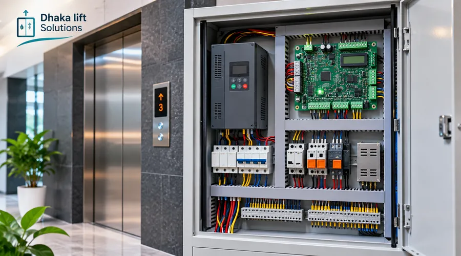
A lift does more than move between floors. It must accept calls, know where the car is, operate its doors and stop at the right landing. Several parts work together to make that happen. The controller coordinates them, but it does not replace the lift's separate safety protections.
Quick answer
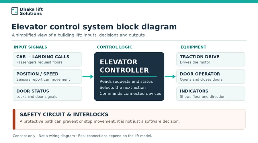
An elevator control system block diagram shows how calls and sensor signals reach the controller, and how the controller sends commands to the traction drive, door operator and indicators. A separate safety circuit can prevent or stop movement when a protective condition is not met. The diagram below explains the main relationships, not the wiring for a specific model.
Elevator control system block diagram
Read the picture from left to right. The left side provides information. The controller makes an operating decision. The equipment on the right carries out the command. The safety circuit remains a protective part of the system rather than a simple software checkbox.
What each block tells you
| Block | Main job | What to remember |
|---|---|---|
| Car and landing calls | Tell the system which floor is requested. | A button sends a request; it does not directly power the motor. |
| Position and speed feedback | Tell the system where and how the car is moving. | The sensor type depends on the lift design. |
| Controller | Chooses the next action and coordinates equipment. | Its logic and connections are model-specific. |
| Traction drive and motor | Control and produce movement. | The drive is not the same part as the controller. |
| Door operator and indicators | Operate doors and show lift status. | Door-lock feedback matters as much as door commands. |
| Safety circuit | Provide protective stopping or movement-inhibit functions. | Never treat it as a circuit that can be bypassed to clear a fault. |
What happens when someone presses a floor button?
Imagine a visitor on the ground floor calling a passenger lift. In a typical automatic system, the sequence is roughly as follows:
- The call is registered. A landing button sends a request to the controller.
- The controller checks the lift's state. It considers the car position, existing calls and the information available from connected devices.
- Movement must be permitted. Door-lock and safety conditions must be satisfied as required by that particular system.
- The drive receives a movement command. It controls the traction motor according to the selected operating arrangement.
- Feedback is monitored. The system uses position and speed information to control travel and stopping.
- The lift arrives and serves the call. After the permitted stop, the door system operates and the floor indicator updates.
This is a useful way to understand a normal trip. It is not a commissioning sequence, fault-reset procedure or guide to changing electrical connections.
What is inside an elevator control panel?
A control cabinet is often mistaken for one large electronic board. In practice, it may hold several devices with different jobs. The layout varies with the manufacturer, lift type and whether the control and drive functions are integrated.
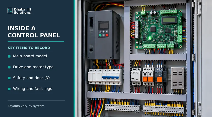
- Main control board: handles requests, operating logic, input signals and output commands.
- Drive or inverter: regulates motor operation where that technology is used. Some lift systems combine drive and control functions.
- Power and switching devices: may include protection devices, contactors, relays and power supplies.
- I/O and communication connections: connect calls, panels, sensors, door systems and other equipment.
- Service information: drawings, model labels and fault records help a qualified technician identify the installed arrangement.
For part identification and supply enquiries, the separate elevator controller and control-panel page is the relevant commercial resource.
Why do elevator controller diagrams look different?
There is no single diagram for every passenger, hospital or goods lift. Three common approaches explain much of the variation.
Older relay-based controls
Some older lifts use substantial relay and contactor logic. A drawing may focus on contacts, coils and separate circuits rather than a single central processor. Repair decisions depend on the condition of the whole installation, not just its age.
Microprocessor or integrated controls
Many modern lifts use electronic control boards, digital inputs and communication modules. Some designs also integrate the drive. A simplified diagram may show fewer boxes even though many functions are still present inside the system.
PLC or distributed control arrangements
Other systems use a programmable controller or several connected modules. This can change where signals are processed and how the drawing is divided. A building with several lifts may also have group-dispatch logic that coordinates calls between cars.
One common mix-up: VVVF describes a method of controlling motor voltage and frequency. It is not a name for every part of the lift controller. See the VVVF drive explainer for that narrower topic.
How does the safety circuit fit into the diagram?
A standard operating command and a protective safety function are not the same thing. Door locks, limit devices and other safety-related contacts or monitored systems can prevent unsafe movement. Their exact arrangement depends on the installed lift and its approved design.
A simplified block diagram may place the safety circuit beside the controller. That is intentional: it reminds the reader that a controller's request to move is not, by itself, permission to move. The protective path must work as intended.
Safety note: A stopped lift, open cabinet or fault indication is not an invitation to bridge a contact, reset a drive repeatedly or test live circuits. Lift control equipment can contain hazardous voltage and stored electrical energy. Inspection, isolation, repair and testing belong to competent elevator personnel following the correct manufacturer procedure.
What should be checked before replacing a controller?
A new board that looks similar may use different terminals, firmware or communication signals. Before buying equipment, a building manager can help the technical team gather reliable information without opening or working inside live equipment.
- Controller make, model and available drawings
- Lift type, number of stops and operating pattern
- Drive, traction motor and brake details
- Encoder or other position-feedback arrangement
- Door operator and landing-door interfaces
- Car and landing panels or communication modules
- Known fault history and parts already replaced
- Available service support and compatible spare parts
The actual replacement plan should be set by a technical assessment. It may involve one component, a full cabinet or linked equipment, followed by configuration and verification. For a broader scope, use the dedicated controller and VVVF modernization page.
What matters for a lift in Bangladesh?
In apartment towers, hospitals and busy commercial buildings, the right control arrangement depends on traffic, door usage, the installed machinery and how the lift is maintained. A good system on paper can still be a poor replacement choice if its parts and support are hard to obtain.
During a site review, ask about power quality, earthing, ventilation, moisture and dust around the equipment. These conditions need checking against the manufacturer's limits. Do not assume that a fault shown on the controller display proves the controller board itself has failed; wiring, door devices, feedback equipment and power conditions may be involved.
Keep the latest wiring drawings and component records with the lift's maintenance documents. Those records can save considerable time when a fault happens later.
Three mistakes people make when reading lift diagrams
- Calling the drive the controller. The controller decides what should happen; the drive deals with motor control. Some products integrate both, but the functions remain distinct.
- Treating a block diagram as a wiring diagram. A block shows relationships. It does not give conductor sizes, terminal numbers or safe installation instructions.
- Assuming an error code identifies a bad board. A code is a diagnostic clue. The cause may sit in a door circuit, sensor, connected drive or power supply.
Questions about elevator control diagrams
Is the controller the same as a VVVF inverter?
No. The controller coordinates the lift's operating logic, while the VVVF inverter controls the motor's electrical drive. Some products combine the two functions in one unit.
Can one block diagram be used for every lift?
No. It is useful for learning the main functions, but actual connections differ by model, drive type, door system, communication design and safety architecture. Use the manufacturer's drawing for the installed lift.
Can a faulty elevator controller be replaced without changing the motor?
Sometimes. It depends on motor and drive compatibility, feedback signals, brake control, door interfaces, safety functions and the existing equipment's condition. A technical assessment is needed before deciding.
What should I send when asking about a controller fault?
Share the lift model if known, number of stops, fault symptoms, error messages, repair history and existing equipment photos taken safely by authorized personnel. Avoid opening energized equipment to take pictures.
Need help identifying a lift controller?
Send the available controller model, lift details and fault history. Dhaka Lift Solutions can review your enquiry and discuss the next technical step without assuming the whole system needs replacement.
Discuss Your Controller Requirement